Hackaday Useful Tools Links

Hackaday Useful Tools Links
So I am an avid reader of Hackaday for a long time now and they have been putting out a lot of great introductions to tools and processes to get makers up to speed on the resources that are available. This is just a splattering of links that I have found lately that you guys might be interested in.
DC Motors
Lessons in Small Scale Manufacturing
Grinding Gears: Figuring out gear ratios
Tools of the trade: Injection Molding
Are todays engineers worse?
How to nail a technical presentation
Tools of the trade: Vacuum Forming
The Art and Science of Bending Sheetmetal
A how-to of designing, fab, and assembly with structural framing systems (t slot)
Machine learning foundations
A machine shop in a box
How to: Cold resin casting
Join the GUI generation: Qtcreator
Do you guys have any other great resources that you’d like to share and/or are you enjoying this type of content?
More Posts from T-sci-eng and Others

How did the Greeks know ?
Greeks had a strong geometric approach towards problems and as a result their methods are very intuitive.
In this post, we will look at the Method of exhaustion formulated by Archimedes that stands out as a milestone in the history of mathematics
Method of Exhaustion - Archimedes

Source
In order to find the bounds of pi, Archimedes came up with a remarkably elegant ‘algorithm’, which is as follows:
Lower bound
Inscribe a n-sided polygon in a circle —> Measure its perimeter(p) —> Measure its diameter(d) —> pi_min = p/d —-> Repeat with n+1 sides.
Upper bound
Circumscribe a n-sided polygon in a circle —> Measure its perimeter(p) —> Measure its diameter(d) —> pi_max = p/d —-> Repeat with n+1 sides.
And by following this procedure one could obtain the upper and lower bounds of pi !
Heres an animation made on geogebra for a circle of diameter 1. Watch how the lower and upper bounds vary.

Archimedes did this for a 96 sided polygon and found the value of pi to be between 3.14103 and 3.1427. This is a good enough approximation for most of the calculations that we do even today!

Happy Holidays !

IMPOSSIBLE! Right? You may have heard “the interior angles of a triangle always add up to 180 degrees”. This is not always true. Check out the second image, it shows a triangle with 3 right angles for a total of 270 degrees!
It is true in flat Euclidean geometry (the geometry you probably learned in school) however. But there are so many other geometries out there! You may be thinking, are other geometries real though? A mathematician would argue they are just as real as the typical flat geometry you know and love (or hate). These alternative geometries can be practically useful too!
The images above show triangles in spherical geometry. Those aren’t triangles though! Oh but they are! A triangle is just a polygon enclosed by three lines. Looks like it fits the criteria. Wait but those aren’t lines, they are curved! Ah yes. I argue that these are, for all intents and purposes, just as good as lines. We need to ask: What is a line? A line is so basic to us we may not know how to describe it. I offer this definition: A line is the shortest path between 2 points. The 3 curves that make the triangle above are in fact the shortest paths from one vertex to the other on the surface of the sphere (they just so happen to be on circumferences of the sphere, which are often referred to as great circles). So it may be more useful to think of lines, in general, as length minimizing curves. In conclusion, we would consider the shape above to be a triangle as it is enclosed by 3 length minimizing curves on a surface.
Spherical geometry can be very useful; think about the Earth. To reduce travel time, airplanes would want to travel along great circles as they are the shortest paths from one place to another. Additionally, this type of thinking (rethinking straight lines as length minimizing curves) is central to Albert Einstein’s general theory of relativity.
read more at http://staffrm.io/@missnorledge/35H6cS1T52

Proof without words - Pi
This was intended to be posted on Pi-day earlier this month, but somehow that didn’t happen.
Hope this beautiful pi gif on this sizzling Saturday puts a smile on your face and guides you through the day.
Have a good one!
Photo credit: Lucas V. Barbosa via Wikimedia Commons
** FYP’s Pi-day post ( if you are interested )
On the direction of the cross product of vectors
One of my math professors always told me:
Understand the concept and not the definition

A lot of times I have fallen into this pitfall where I seem to completely understand how to methodically do something without actually comprehending what it means.
And only after several years after I first encountered the notion of cross products did I actually understand what they really meant. When I did, it was purely ecstatic!
Why on earth is the direction of cross product orthogonal ? Like seriously…
I mean this is one of the burning questions regarding the cross product and yet for some reason, textbooks don’t get to the bottom of this. One way to think about this is :
It is modeling a real life scenario!!
The scenario being :

When you try to twist a screw (clockwise screws being the convention) inside a block in the clockwise direction like so, the nail moves down and vice versa.

i.e When you move from the screw from u to v, then the direction of the cross product denotes the direction the screw will move..
That’s why the direction of the cross product is orthogonal. It’s really that simple!
Another perspective
Now that you get a physical feel for the direction of the cross product, there is another way of looking at the direction too:
Displacement is a vector. Velocity is a vector. Acceleration is a vector. As you might expect, angular displacement, angular velocity, and angular acceleration are all vectors, too.
But which way do they point ?

Let’s take a rolling tire. The velocity vector of every point in the tire is pointed in every other direction.
BUT every point on a rolling tire has to have the same angular velocity – Magnitude and Direction.
How can we possibly assign a direction to the angular velocity ?

Well, the only way to ensure that the direction of the angular velocity is the same for every point is to make the direction of the angular velocity perpendicular to the plane of the tire.
Problem solved!

We started looking at fluctuating loads last time - that is, loads that feature some combination of non-zero mean and alternating stresses - and how to account for them using a Goodman diagram. Let’s re-examine the bracket design problem we did earlier. This time, instead of a fully-reversed load, we’ll assume a fluctuating load with a mean force of 200 lbs, a minimum force of 50 lbs, and a maximum force of 350 lbs. We’ll say the dimensions of the bracket are those we calculated earlier that could handle the fully reversed load. (Problem adapted from Machine Design: An Integrated Approach, 4th Ed., by Robert L. Norton.)
Most of the calculations we did earlier will still hold. We won’t need to recalculate the endurance limit or stress concentration factors. The only new things we need to do are calculate the mean and alternating stresses and the new safety factors.
First step is to calculate the mean and alternating force.

From here, we get the mean and alternating moment.

We’re dealing with a situation of simple bending, so we can calculate mean and alternating stress using the basic bending stress equation.

The geometry of the part hasn’t changed, so we’ll apply the same stress concentration factors that we used before.

Great. We’ve got our new stresses. Now we need to figure out safety factors. As we mentioned earlier, this is now a slightly more complicated proposition. Which safety factor is appropriate will depend on how the alternating and mean stress behave in relation to each other. The possible failure states are shown as points A, B, C, and D on the Goodman diagram for this situation.

We’ll step through all the possible situations one by one using the new stresses we calculated and the endurance limit we got earlier.
Case 1: Constant alternating stress, variable mean stress.

Case 2: Variable alternating stress, constant mean stress.

Case 3: Alternating and mean stress are proportional to each other.

Case 4: Alternating and mean stress vary independently.
We take the worse case, with the failure state F being as close as possible to the current stress situation.

Our design will survive all four cases. Note that Case 4 is always the most conservative case - if you don’t know what your stresses are going to do, this is the one to go with.


Composites: Papercrete
Composites are materials composed of other materials in combination, often with a matrix that binds together fibers of some kind. Papercrete gets its name from its components, paper and concrete, though it is technically composed of cement, not concrete. In papercrete, a composite of paper and cement, the cement makes up the binding matrix that holds the paper fibers together.
Paper is composed of a natural polymer, cellulose, the structure of which can be seen in the bottom image above and fibers of which can be seen in the top left and middle right images. The fibers get coated with cement, often Portland cement, and lend strength to the new material that could not be found in the cement alone. (Paper is not only made of cellulose, but it is a key component which makes papercrete possible. Aside from paper and cement, papercrete is also made with water and some form of sand or earth - other materials can be used as well, just like in concrete).
The material resulting from this mixture, papercrete, has excellent sound absorption, is flame and fungus retardant as well as bug and rodent repellent, and is relatively light. More flexible then rock or regular concrete, papercrete is useful in earthquake prone areas. Though not the best load-bearing material, papercrete is a great insulator. Like any composite however, the exact formula used to produce the material can alter the properties significantly. Adding sand or glass strengthens papercrete and makes it more flame retardant, but also increases its weight.
One of the beneficial things about papercrete is that almost any paper can be used to create it - cardboard, magazine paper, junk mail, newspaper, and other forms. Some work better than others but almost all can be used. Using waste papers such as these prevents them from entering landfills and allows paper to be recycled in a different way.
Downsides of papercrete include its lower strength and durability, as well as the fact that - as of now - there is no code or standardization to its manufacture or use, limiting the projects it can be used in. A fair amount of papercrete is made by individuals working on ‘do it yourself’ projects.
Sources: ( 1 - images 1, 2, 4, and 5 ) ( 2 ) ( 3 )
Image sources: (Middle left)

A sponge can’t soak up mercury. (Video) Facebook | Instagram | Scary Story Website
On the cross product
Understand the concept and not the definition.

If you have studied vectors, then the notion of a cross product is something that you might be familiar with.
Although it is taught in many colleges and schools in its mathematical glory, this post aims to supplement the same but with an real-life example.
The cross product

The magnitude of the cross product is the area of the parallelogram with two sides A and B.
The orientation of the cross product is orthogonal to the plane containing this parallelogram.
Why on earth is it orthogonal ? Like seriously…
I mean this is one of the burning questions regarding the cross product and yet for some reason, textbooks don’t get to the bottom of this.
It is modeling a real life scenario!!
The scenario being :
When you try to twist a screw inside a block in the clockwise direction like so, the nail moves down and vice versa.

i.e When you move from the screw from u to v, then the direction of the cross product denotes the direction the screw will move.

That’s why the direction of the cross product is orthogonal. It’s really that simple :D

Have a good day!
A2A : Anonymous
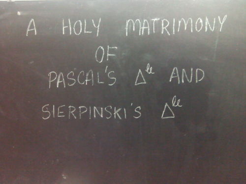


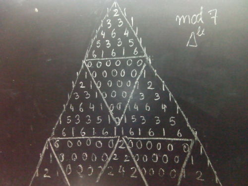
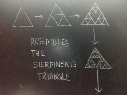
Nature manifests itself in patterns. The interweaving of math with these patterns produces euphoria
What do you see ? Let use know in the comments :)
Quench your thirst for knowledge with:
More about Pascals triangle and Binary Trees - Vihart
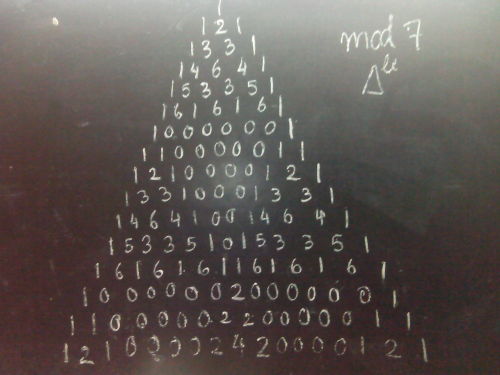
Scary Sierpinski Skull Time
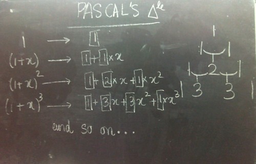
Mathematical secrets of the pascal’s triangle
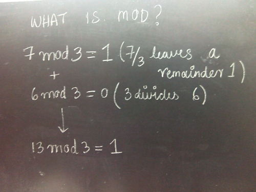
Code to generate Pascal’s triangle mod in Python

It’s a technicolour dreamcoat for your crisp packet – a strong, flame-retardant and airtight new material that mimics mother of pearl.
The natural version, also called nacre, is found on the inner shell of some molluscs, where it is built up of layers of the mineral aragonite separated by organic polymers such as chitin. It is remarkably strong, without being brittle or dense.
We would like to use nacre and similar materials as a protective coating in many situations. However, making them is a slow and delicate process that is difficult to recreate at any useful scale. Artificial nacre-like materials are usually painstakingly built up layer by layer, but Luyi Sun at the University of Connecticut in Storrs and his colleagues found a way to do it all in one go.
Continue Reading.
-
 roofgeese liked this · 8 months ago
 -
 ellswips reblogged this · 8 months ago
 -
 bellaskhakhiskirt liked this · 1 year ago
 -
 catastrophe223 reblogged this · 2 years ago
 -
catastrophe223 liked this · 2 years ago
-
 carrotcakeforbreakfast reblogged this · 2 years ago
 -
 xarcadeassassin liked this · 3 years ago
 -
 spheroid liked this · 3 years ago
 -
 mold12 liked this · 3 years ago
 -
 thedamsnckbar liked this · 3 years ago
 -
 forcripessake reblogged this · 4 years ago
 -
 mahsunyasar liked this · 4 years ago
 -
 harrigarreett-blog reblogged this · 4 years ago
 -
 kayandthekays reblogged this · 4 years ago
 -
 medicalstudy liked this · 4 years ago
 -
 anxvu liked this · 4 years ago
 -
 flegia liked this · 4 years ago
 -
 4h-dimension liked this · 4 years ago
 -
 michelle01411 liked this · 4 years ago
 -
 lillieandnova reblogged this · 5 years ago
 -
 wildtides liked this · 5 years ago
 -
 epsilon-42 liked this · 5 years ago
 -
 vulcansweep liked this · 5 years ago
 -
vulcansweep reblogged this · 5 years ago
-
 thepreternaturalpragmatist liked this · 5 years ago
 -
 darkballoonstuden liked this · 6 years ago
 -
 repaser liked this · 6 years ago
 -
 vestigial-wanderer liked this · 6 years ago
 -
philshifleyme liked this · 6 years ago
-
 robotclube liked this · 6 years ago
 -
 georgie---mitchell liked this · 6 years ago
 -
 kingmac96-blog liked this · 6 years ago
 -
 meriteraitnoel liked this · 6 years ago
 -
 brandonthomasstuff-blog reblogged this · 6 years ago
 -
 pitchers-0-stuff liked this · 6 years ago
 -
 dingdongtoolong reblogged this · 6 years ago
 -
 nicks--world-blog1 reblogged this · 6 years ago
 -
 someone-is-online liked this · 6 years ago
 -
 caffeinatedinsanity reblogged this · 6 years ago